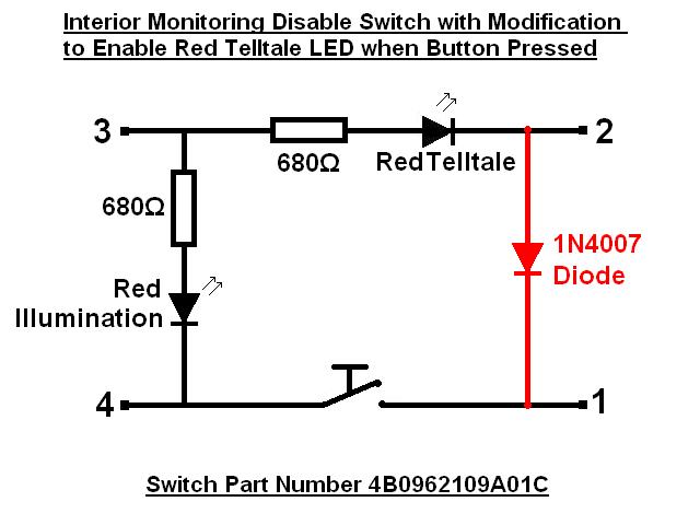
This is the circuit diagram for the 4B0 962 109 A 01C version switch used in the .:R32.
NOTE - other part number switches may have different internal wiring.
The diode is required to be connected from Pin 2 to Pin 1 of the switch.
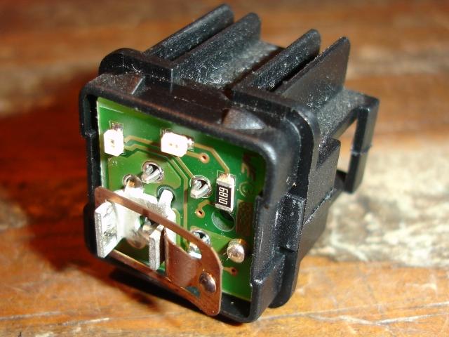
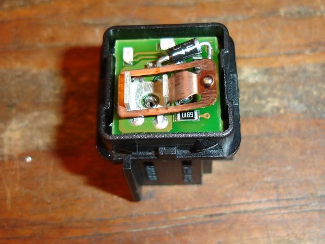
Interior Monitoring Disable Switch disassembled prior to modification:
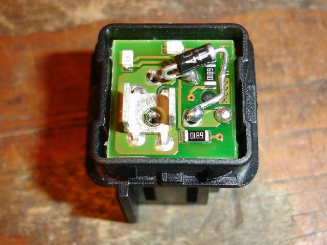
Here are some pictures of how I mounted the diode - note carefully the correct direction for the current flow.
There is quite a bit of space above the circuit board after the switch is pushed back together, so plenty of room to add the diode. Make sure you check this clearance before re-assembly to make sure nothing is touching inside.
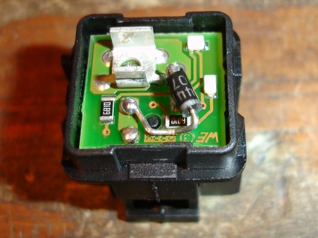
Just a couple of things to watch:
Make sure there is enough clearance for the "clicker" mechanism to work properly.
Especially make sure that the leg of the diode underneath it does not interfere with the points contacting properly.
Also that the body of the diode is clear of the side as well when it operates.
It is, however, also important to mount the diode as close as possible otherwise it may block the red illumination LED from shining into its hole correctly which may cause a shadow on the switch emblem.
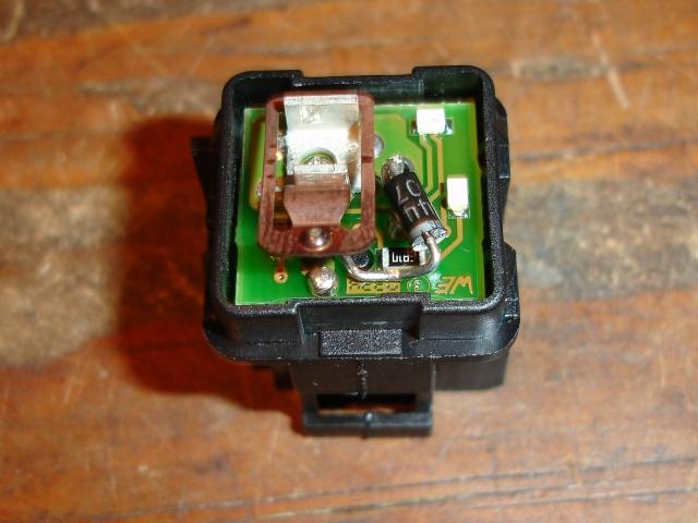
LED now operates when the button is pressed to indicate that the Interior Monitoring System has been disabled.
Normal status just has the emblem illuminated as per standard:

When you are actually depressing the button to disable the Interior Monitoring System, the red telltale will now also illuminate:
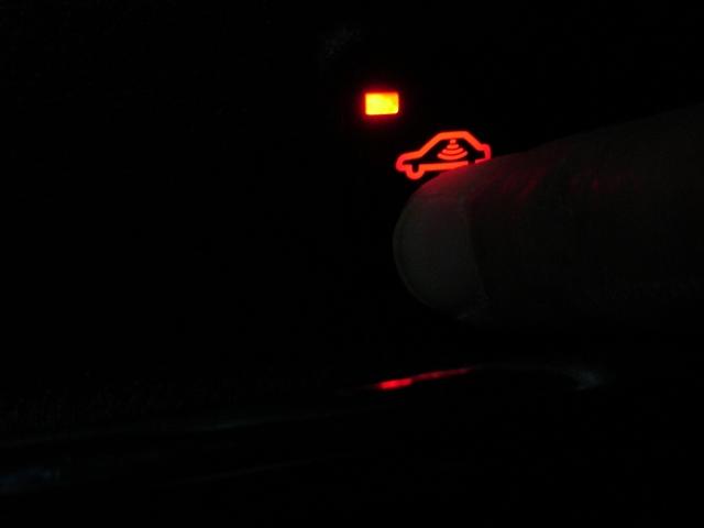
When you release the button, the LED will go off again, but at least you now have a confirmation that the operation was successful!

