Radio Clock Retrofit

It is important to note that this modification only works within the broadcasting range of the DCF77 long-wave time signal transmitter located in Frankfurt am Main in Germany. According to their website, effectively this is up to approximately 2,000 km but depending on atmospheric conditions, the signal may be picked up further away.

Please also note the important information under the "DCF77 Aerial" section below to obtain the correct version that has been tested and works with the circuitry detailed here.

Some Sharan's and T5 Transporter's had the option of synchronising the clock display to this DCF77 time signal. This keeps the clock display within 3 milliseconds of the correct atomic time. This is a fairly common option on Audi's and it is also possible to retrofit to VW instrument clusters as detailed below.

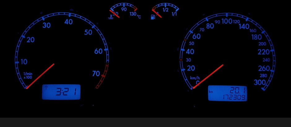
Before you go to all the trouble of installing the components make sure you actually have the "radio tower" icon in the top left hand corner of the LCD clock display. You can see it if you shine a torch onto the display and it will also actually light up if you perform an Output Test of the instrument cluster with VCDS.

To install the components on the front side of the circuit board requires the needles, foils and the white plastic light duct to be removed. The components are also very very small, so some soldering skill is required.

When the radio clock is synchronised to the transmitter time, a small radio transmitter icon appears in the top left corner of the clock display.

The clock button also has to be modified to enable it to be pressed in (similar to trip button). This is to allow you to switch the system on/off manually. This is a useful function if you park your car for extended periods (more than a week) to avoid battery drain. If you do not modify the clock button then you have to switch the function off via EEPROM. Parts to modify the clock button need to be obtained from another cluster!
DCF77 Aerial

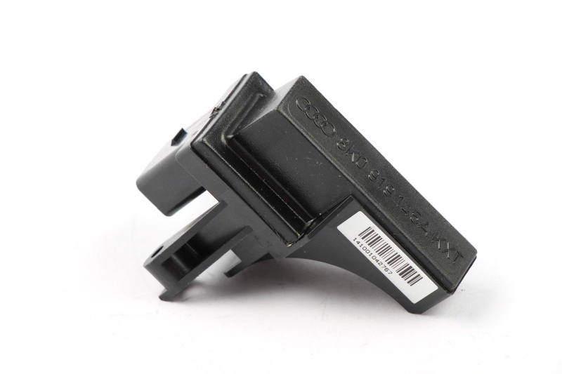
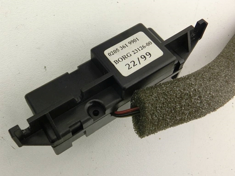
There are a few different versions of the DCF77 aerial used in Audi. The very early versions were internally mounted aerials, either on the inner firewall or attached to the cluster housing. These aerials have been tested and confirmed to work with this modified circuitry. This is the Audi 8N TT version. Note there is no recess to mount them on a VW cluster casing but there is room behind the cluster inside the dash.

Part numbers of the original Audi aerials that are known to work with this circuit design.

4D0 919 145 - note the "4D0" part numbers!

4D0 919 145 A

8N0 919 145

IMPORTANT - THE CIRCUITRY IN THESE INSTRUCTIONS ONLY WORKS WITH THESE EARLIER INTERNALLY MOUNTED AERIALS!!!

The later Audi versions are all mounted externally on the metal reinforcement inside the rear bumper bar. The VW T5 version (same aerial used as latest Audi's) was mounted inside the front bumper on the metal reinforcement.

IMPORTANT - THESE EXTERNAL BUMPER MOUNTED AERIALS DO NOT WORK AS THEY REQUIRE DIFFERENT INTERNAL CIRCUITRY IN THE CLUSTER!!!

4B0 919 145 - note the "4B0" part numbers!

4B0 919 145 A

4B0 919 145 B

8K0 919 145

8K0 919 145 A

8R0 919 145

SMD Components

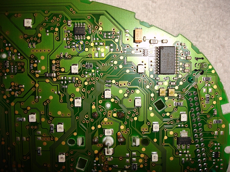
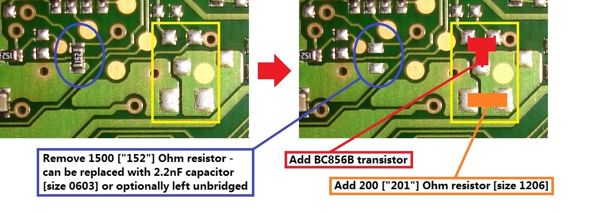
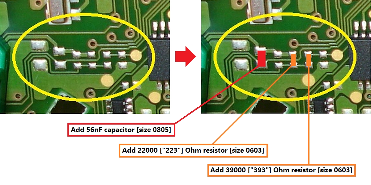
Refer to the photos for position of components.

Front of circuit board:

200 Ohm (SMD-Code 201) - size 1206

PNP Transistor BC856B (SMD-Code 3Bp)

Capacitor 2.2nF - size 0603 (optional) to replace the removed 1.5k Ohm resistor [can leave unbridged]

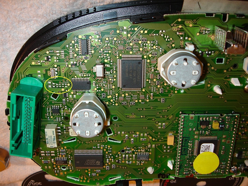
Rear of circuit board:

Capacitor 47nF or 56nF or 68nF or 82 nF or 100nF [I used 56nF] - size 0805

22k Ohm (SMD-Code 223) - size 0603

39k Ohm (SMD-Code 393) - size 0603

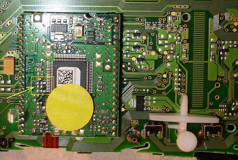
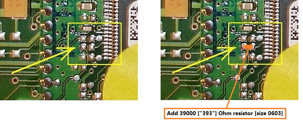
Daughterboard attached to rear circuit board:

39k Ohm (SMD-Code 393) - size 0603

Note that this component is connected to Pin 76 of the NEC chip and is located on the track from the 5th leg up on that side the chip (refer photo)

Clock Button Modification

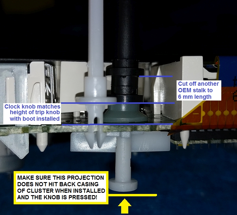
The original clock button only turns left/right. This mod adds the function of being able to also push button in (similar to the existing trip button action). You will need to obtain a second black push button stalk (trip or clock stalk are the same construction, so either okay for this purpose). You will also need the cupped rubber boot off of another trip button that sits against the circuit board. Ensure it still has the conductive ring inside it.

The original black push button is unmodified and is also reused with this modification.

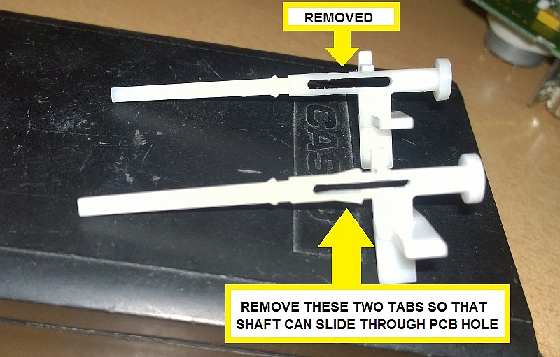
White (internal part) clock stalk modification

Shave off the two barbs that prevent the button from pushing through the circuit board to the back. Make sure it can now pass cleanly through the circuit board smoothly without getting caught up. Also ensure that the rubber boot can also slide freely along the bit where the barbs were removed.

Spare black stalk modification

You will notice the end of the black stalk has a square internal profile to match the white stalk. Run a 4 mm drill down the centre hole approximately 10 mm depth, so that the internal hole is now rounded.

This is so that the internal diameter of this new cut off piece matches the shaft of the white piece and will slide down over the normal stop point of the black button and won't get caught on it.

Cut the flanged end piece off the black knob at 6 mm overall height.

Insert the white stalk into the circuit board and install the cupped rubber boot. Again ensure it still has the conductive ring inside it!

Slide the new cut off black piece onto the white stalk with the flat flange towards the rubber boot, past the normal stop point. As you slide it over this "stop" point you can spin it 45 degrees first so that the original locking tabs dont get caught on the locking barbs for the black button.

Sit it against the top of the rubber boot (uncompressed, just touching)

Clip the original black stalk fully into position until locked in place as normal.The new black piece should be now pushed up fully against the original stalk so there is no gap. All being correct, the black piece should be an interference fit to the white shaft, so won't move in practice.

The new stalk should now rotate left/right and also push in and spring back in the same manner as the trip button does. Test prior to installing circuit board back into the rear casing to make sure the new stalk can be pushed in enough to activate the push function correctly (contact ring inside rubber boot touches the circuit board).

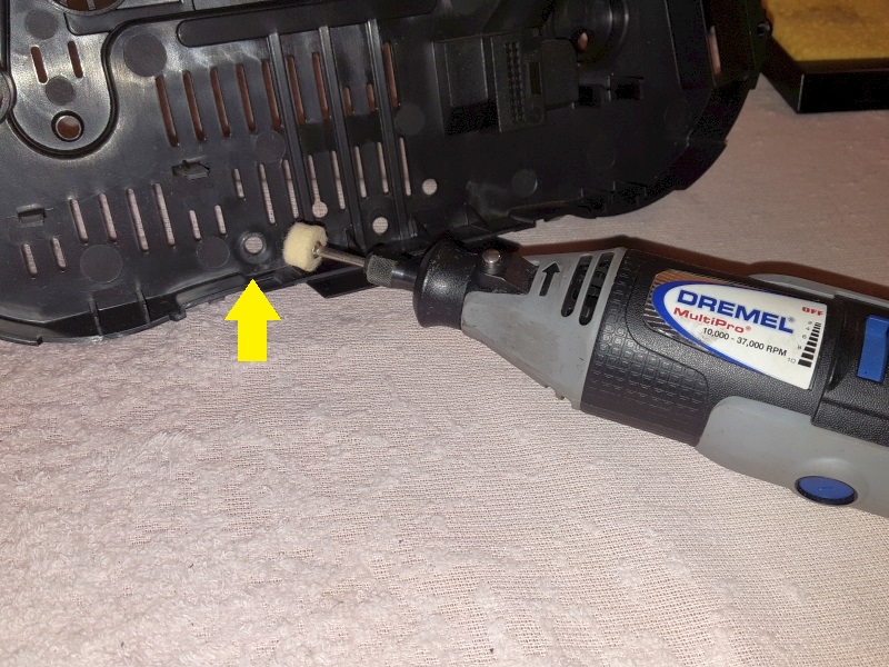
You will note on some rear cluster casings there is an extension tube sticking up exactly behind the original clock knob position on the inside of the casing. This was to stop the original button from being pushed at all. I used a dremel and "spot faced" the raised lip until it was flush with the casing.

Test to ensure that you can still press "in" enough to compress the rubber boot and give contact with the rear casing now in place. The white pad on the end of the white stalk shaft stays unmodified and still acts as a stop for the shaft against the back casing.

Wiring connections

T32a (green) on cluster

Pin 1 - Radio Clock 5V

Pin 3 - Radio Clock (Data)

Pin 10 - Radio Clock Earth

Audi DCF-77 Aerial

Pin 1 - Radio Clock Signal (Data)

Pin 2 - Radio Clock 5V

Pin 3 - not used

Pin 4 - Radio Clock Earth

EEPROM Coding

These EEPROM values need to be amended for the Radio Clock to function correctly:

0x064 (sw501 and sw503)

Activate bit 4 = x x x 1 x x x x enables the Radio Clock function.

This is equivalent to enabling the function via Adaption Channel -19- in Audi clusters.

You can only activate the function via EEPROM manipulation on VW, as Adaption Channel -19- is not be available in VW clusters.

Once the function is enabled in the EEPROM, then you can use the (modified) clock button to turn the synchronisation off/on.

This is why the push function is required to be added to the standard VW clock button.

0x1EC (sw501) / 0x21E (sw503) is the byte that controls the options of when/how the synchronisation is done.

Activate bit 4 = x x x 1 x x x x is required to enable the Radio Clock synchronisation procedure.

Bits 0 and 1 are used together.

x x x x x x 1 1 will enable three hourly synchronisation attempts starting from 02:59:30

x x x x x x 1 0 will enable synchronisation attempts every hour at XX:59:30.

Bit 2 being set ( x x x x x 1 x x ) stops any synchronisation occurring if the cluster/ignition is on.

Bit 3 ( x x x x 1 x x x ) appears to be set on T5 clusters that had the Radio Clock function from factory. Function is not exactly known, but should be set.

I ended up using 1B for this byte value.

Care: if your EEPROM already has a value at this byte, adjust the existing value accordingly! For example, some clusters may already have a value of 20 there, so your new value would be 3B.

Other EEPROM values that appear when system is working (for information):

0x1F0 (sw501) / 0x228 (sw503) is the sync period, defaults to 0x0A (= 10 minutes). A value of 0x0F (= 15 minutes) or 0x10 (= 16 minutes) can also be used.

0x1F1 (sw501) / 0x229 (sw503) will store the UTC offset (time zone) set via the left/right click of the clock button (+/- 12 hours).

Normal time is still set via left/right click when Radio Clock function is turned off or not synchronised.

Function

Radio Clock function is disabled/enabled by pressing and holding the clock button in. The display with show "0" or "1" until you release the button.(This is the new function you have enabled by modifying the existing clock button)

The original clock will function normally if it cannot sychronise with the DCF77 transmitter or if the Radio Clock function is disabled.

Initially, as the EEPROM value has been amended, the function is ON by default.

The cluster will attempt to synchronise with the DCF-77 signal depending on the EEPROM value you have selected above. During a synchronisation attempt the icon will flash. If the synchronisation is successful, then the radio transmitter icon will appear steady in the top left of the clock display as per this video:

  • Radio clock sync + UTC adjustment
  • Note that the synchronisation occurs at the 7 second mark in the video. Once synchronised, the left/right clock button can adjust the UTC time zone up to plus/minus 12 hours (as demonstrated in the video from 21 second mark).

    The cluster will attempt a synchronisation every day to confirm the time. The clock will revert to manual time adjustment if the Radio Clock is unable to synchronise again after three days.

    If you use the coding of 0x1B you can trigger a synchronisation attempt at any time by doing the following steps:

    -Turn ON ignition (do not start car)

    -Turn OFF then turn ON radio clock system (push in clock knob to display "0", then press again to display "1")

    -Turn OFF ignition

    Cluster must enter "sleep mode" before it will even attempt a synchronisation. About 30 seconds after "sleep mode" starts, it should try to synchronise time and you will observe the radio clock icon start flashing. The attempt to sychronise will last up to the specified period set in 0x229 [in my case 0x0A which is up to 10 minutes].

    This procedure does not affect the normal operation of the radio clock system, but will allow you to achieve an initial synchronisation easier instead of having to wait overnight. It will also allow an easier synchronisation if you normally park underground etc, as you can do this any time car is out and about.

    Return to Top

    Return to Home Page